Saturday, 28 November 2015

A Deeper Dive into Fibre-Optic Communication.

Fibre-optic communication is a method of transmitting information from one place to another by sending pulses of light through an optical fibre. The light forms an electromagnetic carrier wave that is modulated to carry information. First developed in the 1970s, fibre-optic communication systems have revolutionized the telecommunications industry and have played a major role in the advent of the Information Age. Because of its advantages over electrical transmission, optical fibres have largely replaced copper wire communications in core networks in the developed world. Optical fibre is used by many telecommunications companies to transmit telephone signals, Internet communication, and cable television signals. Researchers at Bell Labs have reached internet speeds of over 100 petabit×kilometer per second using fibre-optic communication.

The process of communicating using fibre-optics involves the following basic steps: Creating the optical signal involving the use of a transmitter, relaying the signal along the fibre, ensuring that the signal does not become too distorted or weak, receiving the optical signal, and converting it into an electrical signal.

Modern fibre-optic communication systems generally include an optical transmitter to convert an electrical signal into an optical signal to send into the optical fibre, a cable containing bundles of multiple optical fibres that is routed through underground conduits and buildings, multiple kinds of amplifiers, and an optical receiver to recover the signal as an electrical signal. The information transmitted is typically digital information generated by computers, telephone systems, and cable television companies.

Transmitter:

The most commonly used optical transmitters are semiconductor devices such as light-emitting diodes (LEDs) and laser diodes. The difference between LEDs and laser diodes is that LEDs produce incoherent light, while laser diodes produce coherent light. For use in optical communications, semiconductor optical transmitters must be designed to be compact, efficient, and reliable, while operating in an optimal wavelength range, and directly modulated at high frequencies.

In its simplest form, a LED is a forward-biased p-n junction, emitting light through spontaneous emission, a phenomenon referred to as electroluminescence. The emitted light is incoherent with a relatively wide spectral width of 30-60 nm. LED light transmission is also inefficient, with only about 1% of input power, or about 100 microwatts, eventually converted into launched power which has been coupled into the optical fibre. However, due to their relatively simple design, LEDs are very useful for low-cost applications.

Today, LEDs have been largely superseded by VCSEL (Vertical Cavity Surface Emitting Laser) devices, which offer improved speed, power and spectral properties, at a similar cost. Common VCSEL devices couple well to multi-mode fibre.

A semiconductor laser emits light through stimulated emission rather than spontaneous emission, which results in high output power (~100 mW) as well as other benefits related to the nature of coherent light. The output of a laser is relatively directional, allowing high coupling efficiency (~50 %) into single-mode fibre. The narrow spectral width also allows for high bit rates since it reduces the effect of chromatic dispersion. Furthermore, semiconductor lasers can be modulated directly at high frequencies because of short recombination time.


A GBIC module (shown here with its cover removed), is an optical and electrical transceiver. The electrical connector is at top right, and the optical connectors are at bottom left.


 Receivers:

The main component of an optical receiver is a photodetector, which converts light into electricity using the photoelectric effect. The primary photodetectors for telecommunications are made from Indium gallium arsenide the photodetector is typically a semiconductor-based photodiode. Several types of photodiodes include p-n photodiodes, p-i-n photodiodes, and avalanche photodiodes. Metal-semiconductor-metal (MSM) photodetectors are also used due to their suitability for circuit integration in regenerators and wavelength-division multiplexers.

Optical-electrical converters are typically coupled with a Trans impedance amplifier and a limiting amplifier to produce a digital signal in the electrical domain from the incoming optical signal, which may be attenuated and distorted while passing through the channel. Further signal processing such as clock recovery from data (CDR) performed by a phase-locked loop may also be applied before the data is passed on.

Fibre cable types:

An optical fibre cable consists of a core, cladding, and a buffer (a protective outer coating), in which the cladding guides the light along the core by using the method of total internal reflection. The core and the cladding (which has a lower-refractive-index) are usually made of high-quality silica glass, although they can both be made of plastic as well. Connecting two optical fibres is done by fusion splicing or mechanical splicing and requires special skills and interconnection technology due to the microscopic precision required to align the fibre cores.

Two main types of optical fibre used in optic communications include multi-mode optical fibres and single-mode optical fibres. A multi-mode optical fibre has a larger core (≥ 50 micrometres), allowing less precise, cheaper transmitters and receivers to connect to it as well as cheaper connectors. However, a multi-mode fibre introduces multi-mode distortion, which often limits the bandwidth and length of the link. Furthermore, because of its higher dopant content, multi-mode fibres are usually expensive and exhibit higher attenuation. The core of a single-mode fibre is smaller (<10 micrometres) and requires more expensive components and interconnection methods, but allows much longer, higher-performance links.

In order to package fibre into a commercially viable product, it typically is protectively coated by using ultraviolet (UV), light-cured acrylate polymers, then terminated with optical fibre connectors, and finally assembled into a cable. After that, it can be laid in the ground and then run through the walls of a building and deployed aerially in a manner similar to copper cables. These fibres require less maintenance than common twisted pair wires, once they are deployed.

Specialized cables are used for long distance sub-sea data transmission, e.g. transatlantic communications cable. 2011–2013 cables operated by commercial enterprises typically have four strands of fibre and cross the Atlantic in 60-70 ms. Cost of each such cable was about $300M in 2011.

Another common practice is to bundle many fibre optic strands within long-distance power transmission cable. This exploits power transmission rights of way effectively, ensures a power company can own and control the fibre required to monitor its own devices and lines, is effectively immune to tampering, and simplifies the deployment of smart grid technology.


Multi-mode optical fibre in an underground service pit.


Amplifier:

The transmission distance of a fibre-optic communication system has traditionally been limited by fibre attenuation and by fibre distortion. By using opto-electronic repeaters, these problems have been eliminated. These repeaters convert the signal into an electrical signal, and then use a transmitter to send the signal again at a higher intensity than was received, thus counteracting the loss incurred in the previous segment. Because of the high complexity with modern wavelength-division multiplexed signals (including the fact that they had to be installed about once every 20 km), the cost of these repeaters is very high.
An alternative approach is to use an optical amplifier, which amplifies the optical signal directly without having to convert the signal into the electrical domain. It is made by doping a length of fibre with the rare-earth mineral erbium, and pumping it with light from a laser with a shorter wavelength than the communications signal (typically 980 nm). Amplifiers have largely replaced repeaters in new installations.

Wavelength-division multiplexing:

Wavelength-division multiplexing (WDM) is the practice of multiplying the available capacity of optical fibres through use of parallel channels, each channel on a dedicated wavelength of light. This requires a wavelength division multiplexer in the transmitting equipment and a de-multiplexer (essentially a spectrometer) in the receiving equipment. Arrayed wave-guide gratings are commonly used for multiplexing and de-multiplexing in WDM. Using WDM technology now commercially available, the bandwidth of a fibre can be divided into as many as 160 channels to support a combined bit rate in the range of 1.6 Tbit/s.

Friday, 27 November 2015

Guided and Unguided Media

Hi all, found some cool info on guided and unguided media. ~ Purvesh


What are Guided and Unguided media?

Telecommunication links  can broadly be classied into two categories, namely, guided media (wired) and unguided media(wireless). Both media are used for short distance (LANs, MANs) and  long distance (WANs) communication.

Guided Media or Wired links:

Examples of Wired Media

As the name indicates, in guided media
  • Electrical/Optical signals are passed through a solid medium (different types of cables/wires)
  • As the path traversed by the signals is guided by the size, shape and length of the wire, this type of media is called guided media. Also, in guided media, the signals are confined within the wire and do not propogate outside of the wire/media.
  • E.g., Copper Unshielded Twisted Pair (UTP), Copper Shielded Twisted Pair (STP), Copper Co-axial cables, Fiber Optic Cables.

Twisted Pair Copper:

  •  It is the most widely deployed media type across the world, as the last mile telephone link connecting  every home with the local telephone exchange is made of twisted pair copper. These telephone lines are reused as last mile DSL access links to access the internet from home.
  • They are also used in Ethernet LAN cables within homes and offices.
  • They support  low to High Data Rates (in order of Giga bits)
  • However, they are effective only upto a maximum distance of a few kilometres/miles, as the signal strength is lost significantly beyond this distance.
  • They come in two variants, namely UTP (unshielded twisted pair) and STP (shielded twisted pair). Within each variant, there are multiple sub-variants, based on the thickness of the material (like UTP-3, UTP-5, UTP-7 etc.)
  • E.g. DSL, 10/100/1000Mbps Ethernet cables

Copper Co-axial Cables

  • Co-axial copper cables have an inner copper conductor and an outer copper shield, separated by a di-electric insulating material, to prevent signal losses. 
  • It is primarily used in cable TV networks and as trunk lines between telecommunication equipments. 
  • It serves as an internet access line from the home. 
  •  It supports medium to High Data Rates
  •  It has much better immunity to noise and hence signal strength is retained for longer distances than in copper twisted pair media.

Fiber Optic Cables

  • Here, information is transmitted by propogation of optical signals (light) through fiber optic cables and not through electrical/electromagnetic signals. Due to this, fiber optics communication supports longer distances as there is no electrical interference.
  • As the name indicates, fiber optic cables are made of very thin strands of glass (silica).
  • As they support very high data rates, fiber optic lines are used as WAN backbone and trunk lines between data exchange equipments.
  • They are also used for accessing internet from home through FTTH (Fiber-To-The-Home) lines.
  • Additionally, they are used even for LAN environment with different LAN technologies like Fast Ethernet, Gigabit Ethernet etc. using optical links at the physical layer.
  •   
    OC-48, OC-192, FTTC, HFC are examples of Fiber Optical links.

Unguided Wireless Media:

Here information is transmitted by sending electromagnetic signals through free space and hence the name unguided media, as the signals are not guided in any specific direction or inside any specific medium.
All unguided media transmission are classified as wireless transmission.
Wireless transmission can be used as the medium in both LAN and WAN environments, as illustrated in the diagrams below:
Two laptops communicating within a LAN using a wireless Access Points
Two laptops communicating via. a long distance WAN using a WiMax Wireless transmission network
Different forms of wireless communication used in the internet vary mainly based on the following attributes:
  • Distance separating the end stations
  • Frequency spectrum used by the electromagnetic signals
  • Line Encoding technique used
Based on these attributes, a wide variety of wireless PHYs and different types of antennaes are used in wireless communication.
The diagram given below illustrates different types of antennaes typically used in wireless communication
Different Types of Antennaes Used in wireless communication
As illustrated in the diagram, antennaes can be of many sizes and shapes. Some of them are point to point antennaes while others are omni-directional antennaes. Even satellites act as giant antenaes in the sky, by receiving and transmitting signals generated from the earth.
Wi-Fi, Wi-Max. 3G are example wireless networks used for internet communication

http://computernetworkingsimplified.com/physical-layer/overview-guided-unguided-media/

Monday, 23 November 2015

Error Detection video and Flow Control

Error Checking Videos

These are some videos that I thought would be useful in Understanding the different types of error checking we did.

Parity Checking


Cyclic Redundancy Check


Checksum was hard to find, so I could not find a relevant one

Here is Flow Control Explained 


Hope this will be useful for revision !

Transmission Media- Revision for 2nd Internal Portion

Transmission Media!-2nd Internal Revision
Data is represented by computers and other telecommunication devices using signals. Signals are transmitted in the form of electromagnetic energy from one device to another. Electromagnetic signals travel through vacuum, air or other transmission mediums to travel between one point to another(from source to receiver).
Electromagnetic energy (includes electrical and magnetic fields) includes power, voice, visible light, radio waves, ultraviolet light, gamma rays etc.
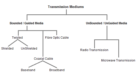
classification of Transmission mediums

Factors to be considered while choosing Transmission Medium

  1. Transmission Rate
  2. Cost and Ease of Installation
  3. Resistance to Environmental Conditions
  4. Distances


Twisted Pair Cable

This cable is the most commonly used and is cheaper than others. It is lightweight, cheap, can be installed easily, and they support many different types of network. Some important points :
  • Its frequency range is 0 to 3.5 kHz.
  • Typical attenuation is 0.2 dB/Km @ 1kHz.
  • Typical delay is 50 µs/km.
  • Repeater spacing is 2km.
Twisted Pair is of two types :
  • Unshielded Twisted Pair (UTP)
  • Shielded Twisted Pair (STP)

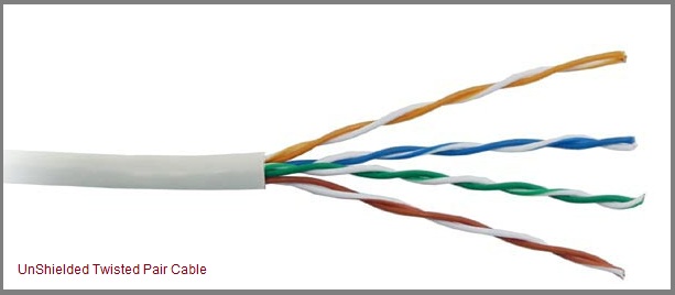
Unshielded Twisted Pair Cable

It is the most common type of telecommunication when compared with Shielded Twisted Pair Cable which consists of two conductors usually copper, each with its own colour plastic insulator. Identification is the reason behind coloured plastic insulation.
UTP cables consist of 2 or 4 pairs of twisted cable. Cable with 2 pair use RJ-11 connector and 4 pair cable useRJ-45 connector.
Unshielded Twisted Pair Cable

Advantages :

  • Installation is easy
  • Flexible
  • Cheap
  • It has high speed capacity,
  • 100 meter limit
  • Higher grades of UTP are used in LAN technologies like Ethernet.
It consists of two insulating copper wires (1mm thick). The wires are twisted together in a helical form to reduce electrical interference from similar pair.

Disadvantages :

  • Bandwidth is low when compared with Coaxial Cable
  • Provides less protection from interference.

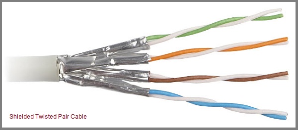
Shielded Twisted Pair Cable

This cable has a metal foil or braided-mesh covering which encases each pair of insulated conductors. Electromagnetic noise penetration is prevented by metal casing. Shielding also eliminates crosstalk (explained in KEY TERMS Chapter).
It has same attenuation as unshielded twisted pair. It is faster the unshielded and coaxial cable. It is more expensive than coaxial and unshielded twisted pair.
Shielded Twisted Pair Cable

Advantages :

  • Easy to install
  • Performance is adequate
  • Can be used for Analog or Digital transmission
  • Increases the signalling rate
  • Higher capacity than unshielded twisted pair
  • Eliminates crosstalk

Disadvantages :

  • Difficult to manufacture
  • Heavy

Coaxial Cable

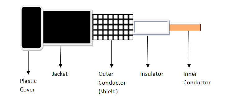
Coaxial is called by this name because it contains two conductors that are parallel to each other. Copper is used in this as centre conductor which can be a solid wire or a standard one. It is surrounded by PVC installation, a sheath which is encased in an outer conductor of metal foil, barid or both.
Outer metallic wrapping is used as a shield against noise and as the second conductor which completes the circuit. The outer conductor is also encased in an insulating sheath. The outermost part is the plastic cover which protects the whole cable.
Coaxial Cable

Advantages :

  • Bandwidth is high
  • Used in long distance telephone lines.
  • Transmits digital signals at a very high rate of 10Mbps.
  • Much higher noise immunity
  • Data transmission without distortion.
  • The can span to longer distance at higher speeds as they have better shielding when compared to twisted pair cable

Disadvantages :

  • Single cable failure can fail the entire network.
  • Difficult to install and expensive when compared with twisted pair.
  • If the shield is imperfect, it can lead to grounded loop.

Fiber Optic Cable

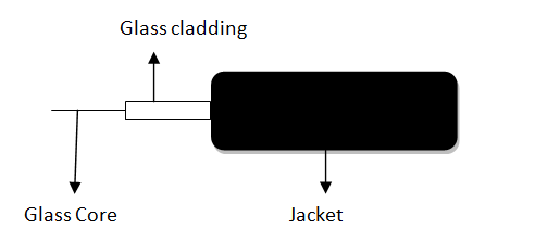
These are similar to coaxial cable. It uses electric signals to transmit data. At the centre is the glass core through which light propagates.
In multimode fibres, the core is 50microns, and In single mode fibres, the thickness is 8 to 10 microns.
The core in fiber optic cable is surrounded by glass cladding with lower index of refraction as compared to core to keep all the light in core. This is covered with a thin plastic jacket to protect the cladding. The fibers are grouped together in bundles protected by an outer shield.
Fiber optic cable has bandwidth more than 2 gbps (Gigabytes per Second)
Fiber Optic Cable

Advantages :

  • Provides high quality transmission of signals at very high speed.
  • These are not affected by electromagnetic interference, so noise and distortion is very less.
  • Used for both analog and digital signals.

Disadvantages :

  • It is expensive
  • Difficult to install.
  • Maintenance is expensive and difficult.
  • Do not allow complete routing of light signals.

UnBounded/UnGuided Transmission Media

Unguided or wireless media sends the data through air (or water), which is available to anyone who has a device capable of receiving them. Types of unguided/ unbounded media are discussed below :
  • Radio Transmission
  • MicroWave Transmission

Radio Transmission

Its frequency is between 10 kHz to 1GHz. It is simple to install and has high attenuation. These waves are used for multicast communications.

Types of Propogation

Radio Transmission utilizes different types of propogation :
  • Troposphere : The lowest portion of earth’s atmosphere extending outward approximately 30 miles from the earth’s surface. Clouds, jet planes, wind is found here.
  • Ionosphere : The layer of the atmosphere above troposphere, but below space. Contains electrically charged particles.

Microwave Transmission

It travels at high frequency than the radio waves. It requires the sender to be inside of the receiver. It operates in a system with a low gigahertz range. It is mostly used for unicast communication.
There are 2 types of Microwave Transmission :
  1. Terrestrial Microwave
  2. Satellite Microwave

Advantages of Microwave Transmission

  • Used for long distance telephone communication
  • Carries 1000’s of voice channels at the same time

Disadvantages of Microwave Transmission

  • It is Very costly

Terrestrial Microwave

For increasing the distance served by terrestrial microwave, repeaters can be installed with each antenna .The signal received by an antenna can be converted into transmittable form and relayed to next antenna as shown in below figure. It is an example of telephone systems all over the world
Terrestrial Microwave
There are two types of antennas used for terrestrial microwave communication :

1. Parabolic Dish Antenna

In this every line parallel to the line of symmetry reflects off the curve at angles in a way that they intersect at a common point called focus. This antenna is based on geometry of parabola.
Parabolic Dish Antenna

2. Horn Antenna

It is a like gigantic scoop. The outgoing transmissions are broadcast up a stem and deflected outward in a series of narrow parallel beams by curved head.
Horn Antenna

Satellite Microwave

This is a microwave relay station which is placed in outer space. The satellites are launched either by rockets or space shuttles carry them.
These are positioned 3600KM above the equator with an orbit speed that exactly matches the rotation speed of the earth. As the satellite is positioned in a geo-synchronous orbit, it is stationery relative to earth and always stays over the same point on the ground. This is usually done to allow ground stations to aim antenna at a fixed point in the sky.
Satellite Microwave

Features of Satellite Microwave :

  • Bandwidth capacity depends on the frequency used.
  • Satellite microwave deployment for orbiting satellite is difficult.

Advantages of Satellite Microwave :

  • Transmitting station can receive back its own transmission and check whether the satellite has transmitted information correctly.
  • A single microwave relay station which is visible from any point.

Disadvantages of Satellite Microwave :

  • Satellite manufacturing cost is very high
  • Cost of launching satellite is very expensive
  • Transmission highly depends on whether conditions, it can go down in bad weather